Week 13: Networking & Communications
Networking & Communications
Advantages of networks include:
- Scalability
- Facilitating the connection of systems across locations
- Improving repairability
- Enabling the simultaneous control of various devices
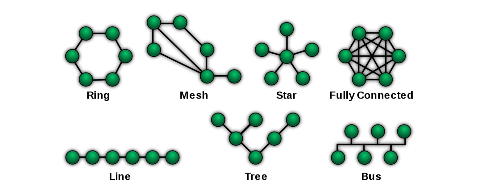
Networks can have different structures:
- Ring
- Bus
- Star
- Mesh
- ...
Networks can be organized locally or have a broader reach. We distinguish between protocol and network. Protocol is the language we use, while the network is what we build.
Important keywords in this context are:
- Location: Refers to the physical or logical place where network components or system modules are positioned. In distributed networks, the location can influence the connection strategy and performance.
- Parallelism: Refers to the ability of a system to perform multiple processes or operations simultaneously, often increasing efficiency and better utilization of resources.
- Modularity: This principle involves designing a system in independent modules that can be developed, tested, reused, or replaced separately to simplify system maintenance and development.
- Interference: In networks, this refers to disruptions or cross-talk between different communication channels that can impair data transmission. Managing interference is crucial for maintaining network performance.
To decide which network we want to build, it is fundamental to know what we want to do with it.
We are talking about serial interfaces. These are interfaces that transmit data bit by bit sequentially. This is the most common form of data transmission in many systems, as it is cost-effective and simple to implement.
There are synchronous and asynchronous communications:
- Synchronous: Data transmission where the sender and receiver are continuously synchronized, often through a common clock.
- Asynchronous: Data transmission without continuous synchronization. Instead, start and stop bits are used to mark data blocks.
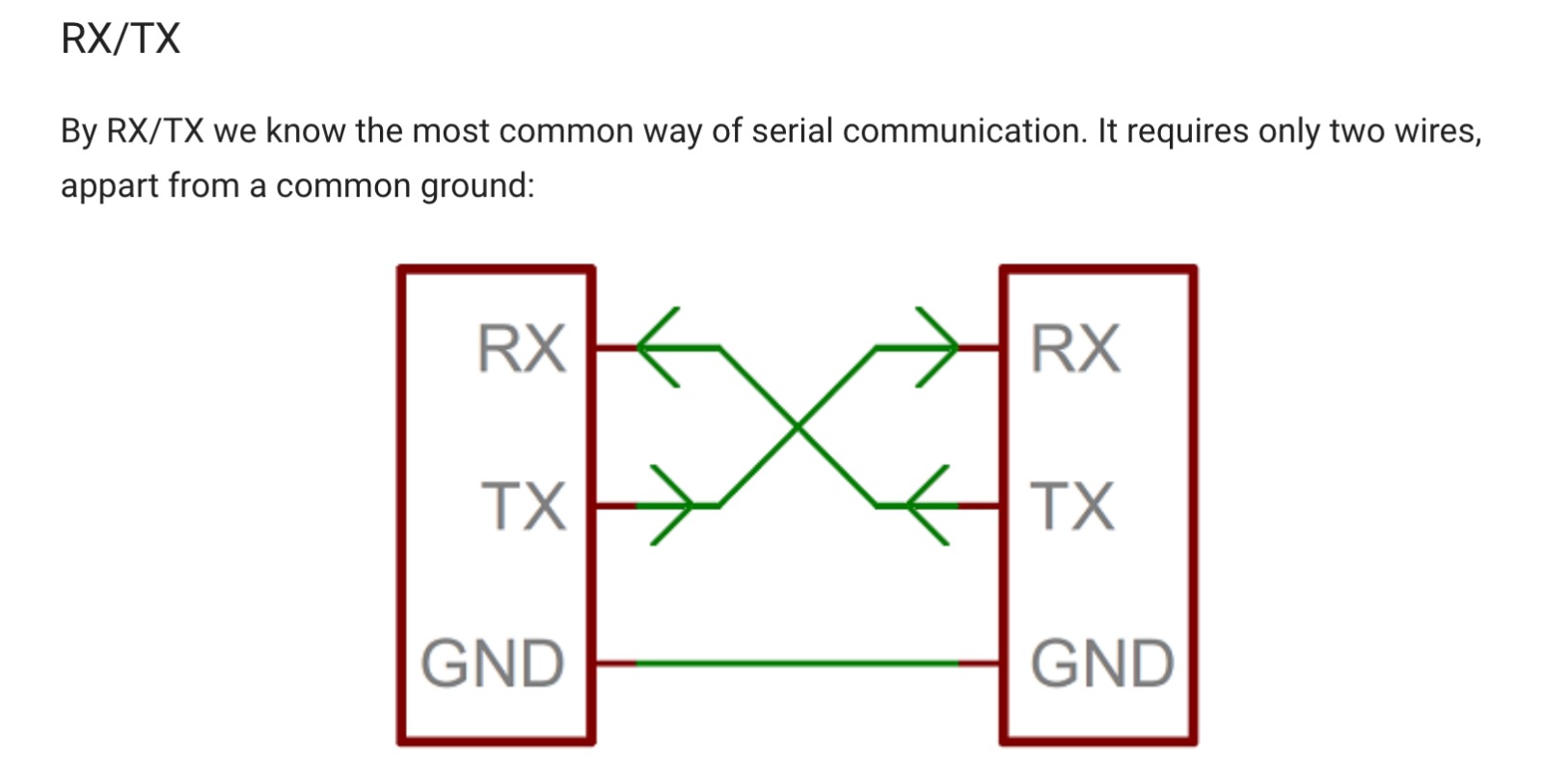
We use RX to receive data and TX to send data. So we have to connect TX with RX, RX with TX and GND with GND.
Under Serial Timing, we understand serial communication and timing to ensure that the sender and receiver are correctly synchronized and data is transmitted error-free.
UART (Universal Asynchronous Receiver-Transmitter): A widely used hardware mechanism for asynchronous serial communication between devices.
USB Serial: An implementation of the USB interface that allows using USB for serial communication, often to connect computers with external devices like microcontrollers or other network devices.
I2C: The I2C (Inter-Integrated Circuit) protocol allows multiple child circuits to communicate with one or more parent circuits. It is intended for short distances within a device. I2C is particularly practical because it supports multiple parents and child without changing the number of required wires. Moreover, only the masters can actively control the data line, preventing childs from blocking the line when another device is transmitting. To enable this communication, a special communication protocol is needed: SPI "Serial Peripheral Interface". With just two wires, you can talk to over 1000 devices.
Wire.begin(); > If nothing is between the brackets, it means the parent, at 9 it means the child.
Wireless communication
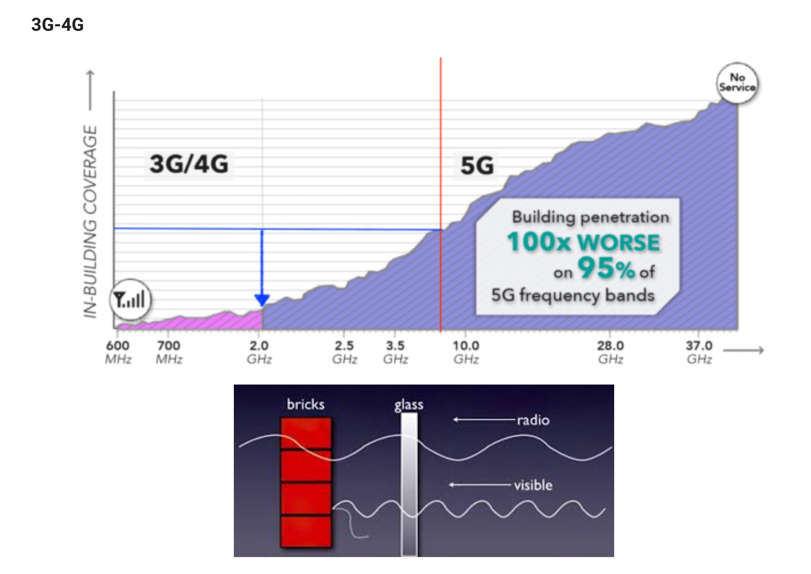
We distinguish between 3G/4G/5G: 3G has the lowest frequency, while 5G has the highest frequency. Therefore, 5G is more powerful, and the data transmission speed is faster. However, these higher frequencies have a shorter range and poorer penetration of solid objects like walls. Thus, 5G networks rely on denser antenna configurations to ensure comprehensive coverage.
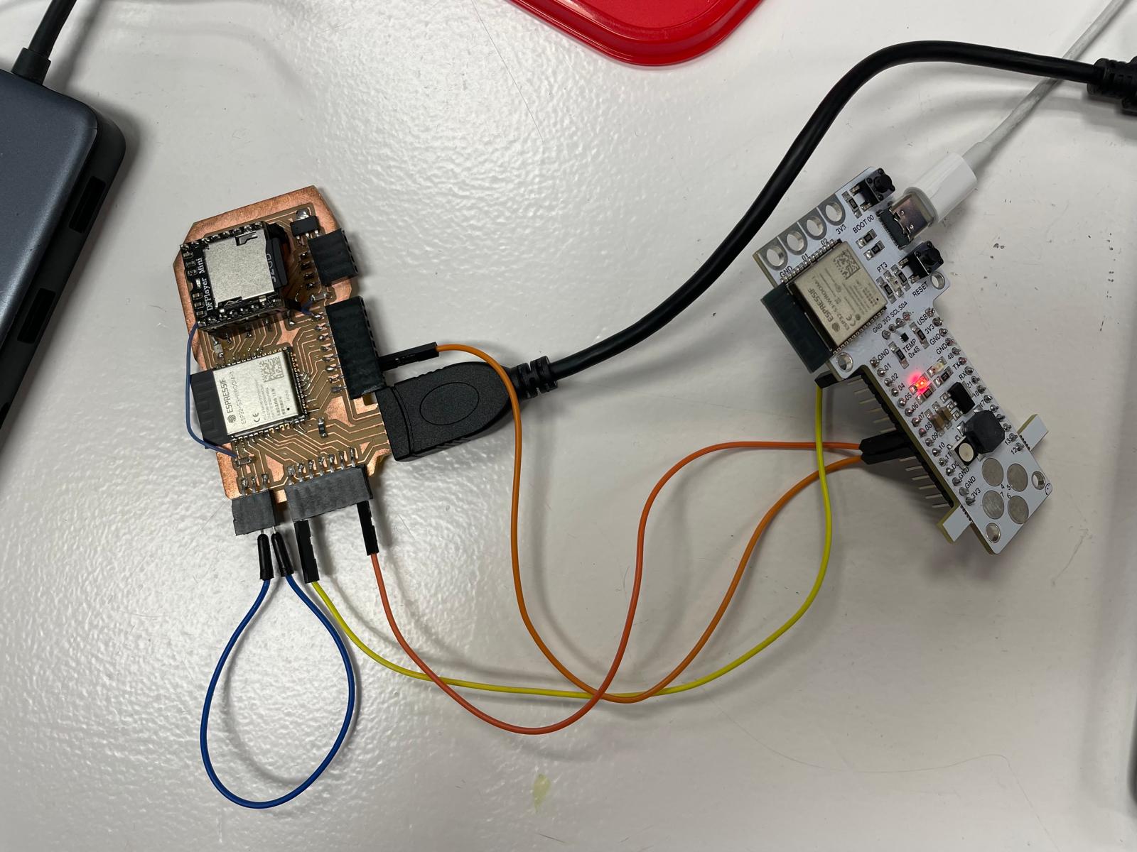
I2C communication with ESP32-S3-WROOM-1
For this week, I wanted to establish I2C communication. For this, I need an SDA pin for data transmission and an SCL for the clock. I am using my board for this assignment, the same board I will use for my final project. I described the creation of the board in Week 8, Electronics Design.
I2C is a wired communication protocol that requires specific pins such as SDA (for data) and SCL (for the clock) to be connected between microcontrollers.
For the ESP32-S3-WROOM-1, it's possible to use almost any GPIO pins for I2C communication due to the flexible GPIO matrix system. The default pins often used for I2C are:
- GPIO8 for SDA (Serial Data Line)
- GPIO9 for SCL (Serial Clock Line)
These default pins are commonly used because they are typically designated for I2C in many ESP32-S3 configurations. Nevertheless, you can remap the I2C pins to other GPIOs if needed, depending on your specific hardware setup and availability of pins.
As a second board, I used the Baruino Board, which also uses an ESP32-S3-WROOM-1 microcontroller. I set up a wired connection and connected the following pins of the two boards:
- Pin 9 to Pin 9
- Pin 8 to Pin 8
- GND to GND
Additionally, I used Pin 1 on the receiver (connected to the LED) and Pin 0 on the sender for the button.
Arduino Code
Sender
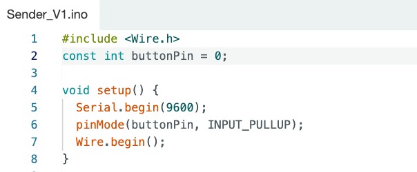
- Include Wire Library: Enables I2C communication.
- Initializes serial communication.
- Sets the button pin as an input with an internal pull-up resistor.
- Configures the Arduino as an I2C sender.
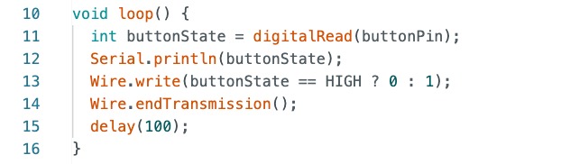
- Reads the button state.
- Prints the button state to the serial monitor.
- Sends the button state over I2C to the receiver device with address 2.
- Delays for 100 milliseconds.
Receiver
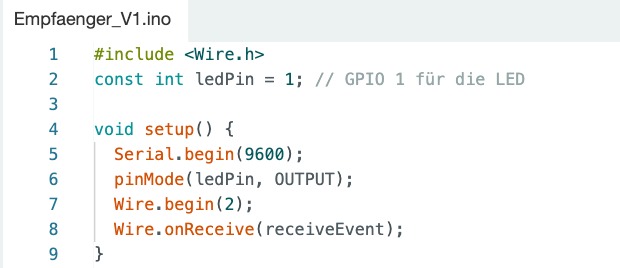
- Include Wire Library: Enables I2C communication.
- Initializes serial communication.
- Sets the LED pin as an output.
- Configures the Arduino as an I2C receiver with address 2.
- Registers the receiveEvent function to handle incoming I2C data.
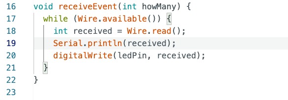
- Reads received I2C data.
- Prints the received value to the serial monitor.
- Controls the LED based on the received value.